- Home
- Products
- Summary & Overview
- Bus Analyzer
- Interface Cards
- FireRepeater
- Connectivity
- IP Cores
- Software
- Accessories
- Solutions
- Support
- News
- Contact
- Company
- Mil1394
- Sitemap
- Search

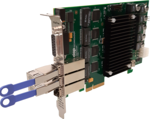
The FireTrac3424bT and FireTrac4424bT feature the FireTrac® family functionality in the widely used PCI Express form factor and host conenctivity. Both use the latest versions off-the-shelf PHY layer silicon (TSB41BA3) together with Dap's FireLink® Extended IP Core. Both cards are also available in an S800 version.
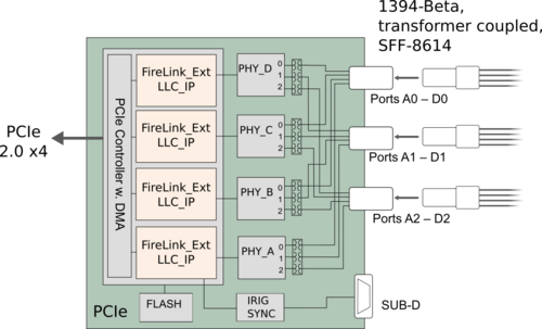
FireTrac3424bT offers a three node (bus) solution whereas FireTrac4424bT features a novel solution with four nodes (buses).
The HW also provides IRIG time-stamping of monitored events and accepts IEEE1344 IRIG-B122 as well as IRIG-B002 inputs.
Both cards are also avaiable in versions supporting S100 as well as S800.
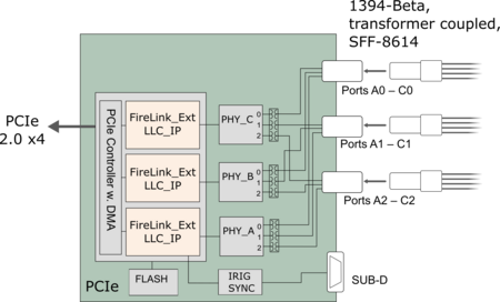
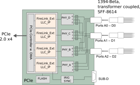
*) Depending on exact model
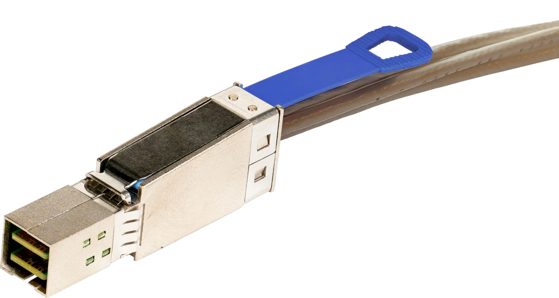
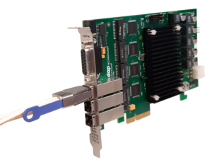
For these versions of FireTrac® DapTechnology has opted to implement an innovative off-board connectivity, rather than the SCSI2 connector (used on the FT3460bT) and FT3x24bT as well as FT4x24bT use SFF-8614 connectors. SFF-8614 originates from the miniSAS HD interconnectivity technology which has proven its benefits with regards to signal integrity, data throughput, durability and usability. Customers will benefit for the selected port-to-connector routing (A0-D0, A1-D1, A2-D2) as the need for cables can be adjusted to the specific usage scenario, therefore simplifying harnesses and reducing costs for unneeded cables.
For example, with just one (1) harness the ‘0”-ports on all 4 nodes (A-D) can be connected as leave nodes. Additional harnesses would only have to be added for daisy-chain or star connectivity.
| Dimensions: |
Half-length, full-height x4 PCIe, 111mm x 167mm |
||
| Weight: | 230 g | ||
| Power Requirements: | 10 Watts (max.) | ||
| Regulatory Compliance: | FCC Class A, CE | ||
| Connections: |
PCI Express 2.0 x4 3x SFF-8614 connectors for transformer-coupled 1394b ports D-SUB connector for IRIG and Sync |
||
| Indicators: | - | ||
| Switches: | - | ||
| Part Number: |
FT3424bT-OPT1-OPT2-[OPT3] or FT4424bT-OPT1-OPT2-[OPT3] |
||
| Options: | OPT1: Operating System
WIN – MS WindowsTM |
OPT2: Personality Profile FFP – Full Personality Profile |
OPT3: Extended Warranty SS - SW extended Warranty |
| Codes: | Export Control: EAR99 HTS: 8471.80.10.00 |
||
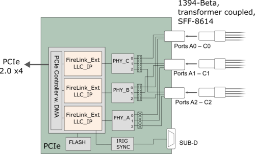
In order to get the best out of the unique feature set of the FireTrac card DapTechnology recommends using the hardware in combination with FireStack, i.e. DapTechnology's home grown software stack.
FireStack optimally supports the hardware and firmware layers embedded into FireTrac. As FireTrac's host interface uses FireLink Extended (and not a standard OHCI Link Layer chip) functionality that has been tailored and optimized for the support of the AS5643 standard brings the combination of FireTrac and FireStack to an entirely new level.
The objective of FireStack’s® 1394 packet handler is to reduce resource burden when receiving and transmitting 1394 packets. The consistent utilization of zero-copy operations greatly enhances the overall system performance. FireStack® provides memory buffers accessible by both the user application and the 1394 Link Layer DMA engine.
For example, when transmitting an asynchronous packet and the user application has filled the memory buffer with the needed packet data, FireStack® will hand the buffer directly to the Link Layer for reading the packet into the packet transmission FIFO without having the CPU copy memory to memory.
Likewise, displaying a video stream from an IIDC camera only requires creation of DMA-capable reception buffers for the video frame data and registration of notification upon filling of a complete frame. Once notified the buffers holding the received data can be accessed directly by the video rendering engine in order to move the data to video card memory.
Inbound Transactions (handling of incoming requests) are defined in two separate methods:
Map Local Memory: The user can "map" a memory buffer to a specific address space. The contents of the memory buffer can be accessed by the user application at any point in time. At the same time when the stack receives a request packet from a remote device it will automatically perform the response operation (read, write or lock) and will send a response packet back to the requester. The user has the option to be notified by the notification callback function when the transaction completes.
Transaction Handler: Similar to the Map Local Memory above the user can "register for" a specific address space instead of "mapping" local memory. When the stack receives a request packet it will call the user-specified handler callback function. The user can then perform any operation within the callback function. Upon returning from the handler callback, the FireStack® may transmit a response packet. The notification callback function will be called after completion of the response process.
This module can be used to perform memory transactions (read, write, lock) on remote nodes. When a memory transaction is initiated FireStack® will automatically determine the maximum speed to the destination node by performing the needed PHY remote accesses.
Outbound Transactions can be used in the following ways with respect to result indication: In Blocking mode the TX functions will not return until the response packet is received and thus making the code sequential. In contrast to that the Non-Blocking mode can be used to initiate a series of “split” transactions i.e. a series of requests that are then followed by the corresponding - but not necessarily sequential - responses.
The Isochronous Streaming modules build on the mechanisms for efficient data processing defined by OHCI and provide a flexible and user-friendly API around it. Linked lists of buffers can be setup by the user application and will be automatically processed by the Link Layer DMA engine. Notification mechanisms are available for buffer and/or packet completion.
An essential feature of FireTrac® is its thin software and firmware layer. In order to be usable in embedded designs having limited resources, great emphasis was given to keep the footprint and host system resource utilization as small as possible. And, in order to optimize and streamline performance, the individual features and functions of FireTrac® are grouped into so-called Personality Profiles. These profiles may be purchased separately so that the user may configure their system based on individual requirements.
The Personality Profiles allow the solution to be adapted for use in embedded systems which typically have limited resources, and/or with powerful host processors that can utilize even the fully featured profile.
The following profiles are available:
The SAE-AS5643 protocol differs from other 1394 protocols because of its stringent timing requirements. Because of potential inaccuracies and unpredictable latencies possible with software implementations, DapTechnology strongly believes that the AS5643 protocol timing is best implemented via a HW extension in the 1394b Link Layer. Therefore, DapTechnology has added the AS5643 protocol timing into FireLink® Extended as an integral module. With this HW support FireLink® Extended is easily capable of meeting the AS5643 frame timing requirements and eliminates the need for complicated interrupt schemes or real-time operating systems typically needed to efficiently use the AS5643 protocol.
The FireStack® software library contains an AS5643 protocol module that can be used to control the AS5643 hardware of FireLink Extended enabled products (e.g. the FireTrac I/O card). Optimized frame timing can be configured and used for both timed transmission and reception.
Frame Timing: FireStack® is very flexible in the way it handles the timing of Start of Frames. Frame synchronization for AS5643 reception and transmission may be configured as either:
In addition to acting as a synchronization “slave”, it is also possible for each bus to act as STOF master and output a sync pulse on an External Sync Pin.
Reception: AS5643 reception provides a filtering mechanism and all incoming packets will be run against a comprehensive verification system. Messages can be filtered on channel number, AS5643 message ID or a combination of both.
Transmission: AS5643 Transmission module can be used to control devices that support AS5643 timed transmission in. FireTrac® offers very accurate transmission timing. The following transmission modes are available:
Streaming messages: Allows writing large or small sets of messages to FireStack® and having them transmitted automatically at specified frame offset times. The provided data needs to contain so called frame separator elements to indicate that the following message needs to be transmitted in the next frame.
Repeating messages: Allows setting up a message that will automatically be transmitted each frame by FireTrac hardware. The user will have a pointer to the actual data of the message and is allowed to manipulate the data at any point in time without having to worry about its timed transmission. This is very useful for AS5643 status messages.
Single messages: Allows simply transmitting a message as soon as possible but exactly at the specified frame offset time. Several messages may be handed to the FireStack® for immediate transmission and the FireStack® will then take care of the actual moment of transmission.
STOF Messages: Allows controlling transmission of STOF messages.
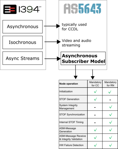
SAE AS5643 describes two types of device categories Control Computers (CC) and Remote Nodes (RN) whose functional definitions depend on the assigned tasks with respect to network communication and integrity verifications. Supporting both device types is an integral objective for FireTrac® and FireStack® and the FireStack API provides feature rich function calls for both categories in parallel. This way the implementer can focus on the AS5643 functional requirements for either CC and RNs. FireStack® doesn’t put the device in a specific operational mode (either CC or RN) but all related functions and functionalities exist in parallel and – for a multi-node device can used independently per node. Example applications are (or will be made) available to demonstrate both scenarios.
However, it is also important to understand that FireTrac® is not just a dedicated “AS5643 device”. It is also a fully compliant IEEE-1394 device. In particular this is important because next to the Async Streams (which are used for the Asynchronous Subscriber Model (ASM)) FireStack® also supports Asynchronous as well as Isochronous Messaging. Both are optional for the usage in AS5643. But due to its guaranteed quality-of-service the Asynchronous messaging seems to be the logical choice for Cross-Channel-Data-Link (CCDL) implementations. And video/audio streaming in conjunctions with ASM traffic is seen as a future growth path for future variants of AS5643.
The FireTrac® product family offers a large variety of options how these I/O cards can be used to start, expand, and grow a simulation environment for AS5643 devices. While architecturally identical, the different channel numbers allow for a vast variety of configurations. The image to the reight presents a few varants hwo a network can be built by using just a few FireTrac cards. The multi-node card archtiecture allows to easily configure the branch structure of nodfes connected to a single CC. Equally, the FireTracs can be used to simulate the aspects of a redundant network.
Please note that the configuration scenarios presented below predominantly address triple redundant network systems, yet can relatively simply be adapted for system redundancies lower or higher than three (3).
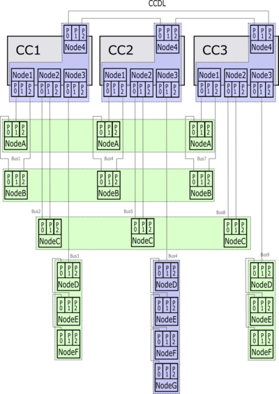
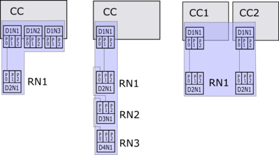
The 4-node version(s) of FireTrac® is perfectly suited for use as a CC. As the picture below demonstrates the 4-node architecture is ideal to simulate a 3-branch CC including the interface for the CCDL. Using three FireTrac® cards (blue) a full and triple-redundant arrangement for control computers can be realized.
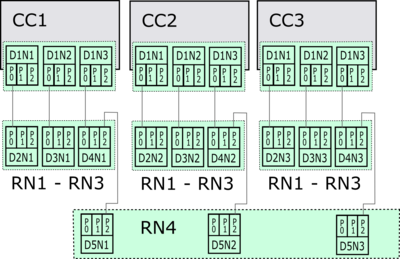
Paired with a triple redundant RN implementation using 3-node FireTrac® (displayed in green) one can easily build a minimal yet expandable instantiation of an AS5643 network consisting of CCs with CCDL and RNs.
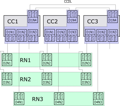
However, the above is only an implementation variant. A 4-node FireTrac® can also be used to simulate single branch bus behavior (left and middle) or mixed CC/RN situation in double redundancy (right).
The 3-node version(s) of FireTrac® is best suited to address triple-redundant and triple-branch architectures when no CCDL is needed. The picture below demonstrates how such a system can be arranged in different RN configurations by using just a few 3-node FireTrac® cards (green).
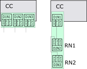
Other variants of how a single 3-node FireTrac® card can be used are depicted below. The left shows a CC devices simulating the triple bus interface (3 CC) whereas the right pictures demonstrates a possible single-branch usages model (CC + 2 RNs).
A single FireTrac can be used to simulate four different AS5643 devices and the separate nodes can be easily interconnected via small Connectivity Dongles which are sold as optional accessories.
In the depicted example, one Dongle (AB-CD, top) connects ports A0 with B0 as well as C0 with D0. Furthermore, an additional Dongle (AD-BC, bottom) can be used to connect B1 with C1. The resulting loop on A1-D1 is automatically resolved with the PHY-level loop healing mechanism.
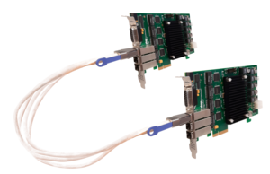
When enlarging the network, two or more FireTracs can be easily interconnected with SFF-SFF harnesses. Such harnesses are available in various lengths.
For optimized installations (labs, test systems, …) these SFF-SFF harnesses can also be configured in single, dual or triple channel variants. Please consult our sales specialists for assistance.



Manual available on request
The following accessories are available for this product:
In order provide a wide variety of connectivity options – either to additional FireTracs or to other AS5643 equipment, DapTechnology is developing a set of harnesses / interconnectivity options.
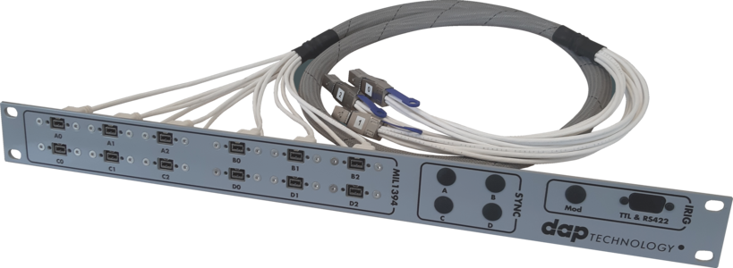
For example the 19”-breakout panel as depicted below offers an extremely flexible way to connecting bus devices via 1394b bilingual sockets. Such a “patch”-panel can also be configured with LEMO or 38999 sockets depending on the customer’s interconnectivity preferences.
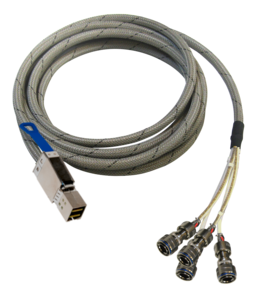
Beside the 19”-panels DapTechnology will offer also a series of “patch-cables”. For examples, the SFF-to-SFF cable shown below can be used to effectively daisy-chain several FireTracs (ports A0-D0 to A1-D1) with just one single harness. Other variants include fan-out cables with Bilingual or 38999 connectivity. No termination variants are also available.
|
For Product(s): FireTrac4x24bT, FireTrac3x24bT |
|||
|
SFF5F419PBLF-IS |
3x SFF-8614 |
12(9)x 1394 Bilingual (female) 9-pin, |
5 feet |
|
The harnesses above are also available in 10ft, 15ft, 20ft and 50ft variants. Warning: The usage of the SFF connectivity in this harness is tailored for IEEE1394 and has a non-standard pinning. It shall only be used in combination with FireTrac. |
|||
|
For Product(s): FireTrac4x24bT, FireTrac3x24bT, FireAdapter4424bT, FireAdapter3424bT |
|||
|
Part number: |
Termination 1: |
Termination 2: |
Length: |
|
The harnesses above are also available in 10ft, 15ft, 20ft and 50ft variants. Warning: The usage of the SFF connectivity in this harness is tailored for IEEE1394 and has a non-standard pinning. It shall only be used in combination with FireTrac. |
|||
|
For Product(s): FireTrac4x24bT, FireTrac3x24bT, FireAdapter4424bT, FireAdapter3424bT |
|||
|
Part number: |
Termination 1: |
Connections: |
Length: |
|
SFFDongleAD&BC |
SFF-8614 | Port Ax connected to Port Dx Port Bx connected to Port Cx |
- |
|
SFFDongleAB |
SFF-8614 | Port Ax connected to Port Bx |
- |
|
SFFDongleAC |
SFF-8614 | Port Ax connected to Port Cx |
- |
|
SFFDongleBC |
SFF-8614 | Port Bx connected to Port Cx |
- |
| Warning: The usage of the SFF connectivity in this device is tailored for IEEE1394 and has a non-standard pinning. It shall only be used in combination with FireTrac or FireAdapter. | |||
|
For Product(s): FireTrac4x24bT, FireTrac3x24bT, FireAdapter4424bT, FireAdapter3424bT |
|||
|
Part number: |
Termination 1: |
Termination 2: |
Length |
| SFF5F4SFF SFF5F3SFF |
as above | as above | 5 feet |
|
The harnesses above are also available in 3ft, 7ft,10ft, 15ft, 20ft and 50ft variants. Warning: The usage of the SFF connectivity in this harness is tailored for IEEE1394 and has a non-standard pinning. It shall only be used in combination with FireTrac. |
|||
|
For Product(s): FireTrac4x24bT, FireTrac3x24bT, FireAdapter4424bT, FireAdapter3424bT |
|||
|
Part number: |
Termination 1: |
Termination 2: |
Length |
|
The harnesses above are also available in 1ft, 3ft, 7ft, 10ft, 15ft, 20ft and 50ft variants. Warning: The usage of the SFF connectivity in this harness is tailored for IEEE1394 and has a non-standard pinning. It shall only be used in combination with FireTrac. |
|||
|
For Product(s): FireTrac4x24bT, FireTrac3x24bT, FireAdapter4424bT, FireAdapter3424bT |
|||
|
Part number: |
Termination 1: |
Termination 2: |
Length |
| SFF5F4LEF SFF5F3LEF |
SFF-8614 | 4x LEMO female 3x LEMO female |
5 foot |
|
The harnesses above are also available in 1ft, 3ft, 7ft, 10ft, 15ft, 20ft and 50ft variants. Warning: The usage of the SFF connectivity in this harness is tailored for IEEE1394 and has a non-standard pinning. It shall only be used in combination with FireTrac. |
|||
|
For Product(s): FireTrac4x24bT, FireTrac3x24bT, FireAdapter4424bT, FireAdapter3424bT |
|||
|
Part number: |
Termination 1: |
Termination 2: |
Length |
|
The harnesses above are also available in a 10ft variant. Warning: The usage of the SFF connectivity in this harness is tailored for IEEE1394 and has a non-standard pinning. It shall only be used in combination with FireTrac. |
|||
|
For Product(s): FireTrac4x24bT, FireTrac3x24bT, FireAdapter4424bT, FireAdapter3424bT |
|||
|
Part number: |
Termination 1: |
Termination 2: |
Length |
| SFF5F4MIF-... SFF5F3MIF-... |
SFF-8614 | 4x 38999* female 3x 38999* female |
5 foot |
|
* Due to numerous options for 38999 connectors (material, size, pinning, keying, lanyard, ...) a detailed connector requirement has to be delveloped as part of the sales process. The harnesses above are also available in 1ft, 3ft, 7ft, 10ft, 15ft, 20ft and 50ft variants. Warning: The usage of the SFF connectivity in this harness is tailored for IEEE1394 and has a non-standard pinning. It shall only be used in combination with FireTrac. |
|||
|
For Product(s): FireTrac4x24bT, FireTrac3x24bT |
|||
|
Part number: |
Termination 1: |
Termination 2: 1x Dsub9 (female): |
Length |
| DSU1F6NT-IS | Dsub15 (male) | no termination, connections as above | 1 foot |
| The harnesses above can also be built in other lengths (e.g. 3ft, 5ft, ...). | |||
Please note that cables for this product need to be purchased separately.
Typically 4 weeks. Please contact sales(at)daptechnology.com for more detailed information.
Standard: 48 months, limited.
Options: Additional 1-year SW/FW Support packages may be purchased.
All products will be supported on a 24 hours response basis and free of charge during the warranty period. For support questions please contact: sales(at)daptechnology.com
Of course you can also call us during our office hours from 9:00 until 17:00 hours (GMT +1:00). Contact Info
For those educational institutions that would like to use our high-specification IEEE-1394 analyzer for educational purposes only, we have a special discount offer. Our FireSpy® software which runs automatically in demo-mode without the use of a FireSpy® has great educational properties. This software can be used for free by everyone and is of great value for learning IEEE-1394. In order to obtain more details about this offer, please contact: sales(at)daptechnology.com
Please contact sales(at)daptechnology.com for current pricing.
| Country | Distributor | Phone | URL |
|---|---|---|---|
| China | BEIJING CESITEK CO., LTD. | +86 10 84177715 | www.cesitek.com |
| Japan | Nacelle Co. Ltd. | +81-3-5921-5099 | www.nacelle.co.jp |
| United States of America | DapUSA, Inc | +1 480 422 1551 | www.dapusa.com |
| South Korea | Realtimewave Co. Ltd. | +82-31-698-2980/2 | www.realtimewave.com |
| all other countries | Dap Technology B.V. | +1-514-453-4111 | www.daptechnology.com |
Click here for a more detailed listing of our Sales Representations.
For the U.S.A., we have as representatives:
| Representative | Territory | Phone | URL |
|---|---|---|---|
| Dap USA Office Arizona | Entire United States of America | +1 480 422 1551 | www.dapusa.com |
To place an order for DapTechnology products, please print one of the following order forms and email it to the corresponding email address:
USA:
Dap USA, Inc.
sales(at)dapusa.com
Download order form
Or contact us by phone: +1 480 422 1551
Rest of the world:
Dap Technology B.V.
sales(at)daptechnology.com
Download order form
Or contact us by phone: +1 480 422 1551