The following pages provide a comprehensive technology overview and intend to provide basic and conceptual understanding about the technology, its benefits and usage scenarios. It references key communication methods that make Mil1394 such a perfect method for avionics control systems and fly-by-wire platforms.

Mil1394 is an approved SAE standard and is backed by some of the very large subcontractors around the world. Ongoing work within the SAE AS-1A workgroup ensures the continued evolution of the existing Standard.
The technology provides several essential high-lights which have contributed massively to reach its strong market position:
The SAE has released the following marketing slides which - on a very high level - summarize the key benefits of the standard. The various sections on this page (and tabs) will add further detail and information to the points mentioned in the slides.
The benefits of the IEEE-1394 standard with AS5643 began with the trade study of I/O technologies developed for the Joint Strike Fighter program. 1394 was originally adopted by the consumer electronics and computer markets for its plug-n-play, real-time streaming (isochronous) and high-bandwidth block storage capabilities. When IEEE-1394b-2002 was being developed several years ago, the Joint Strike Fighter F-35 program began the review of I/O options for its flight control bus. This study considered different versions of IEEE-1394 such as IEEE-1394a-2000 and IEEE-1394b-2002 along with Ethernet, USB2.0, Fibre Channel and MIL-STD-1553. Several criteria were evaluated to determine which technology was best suited for this vehicle management network. These included deterministic behavior, weight, power, volume, latency, topology robustness, software impact, hardware development risk, Failure Modes and Effects Analysis (FMEA) risk assessment, tech-refresh path, both non-recurring and re-occurring costs and, finally, customer acceptance.
AS5643 coupled with IEEE-1394 Asynchronous Stream capability provides a programmable rate-based (time-sliced) protocol with a rate determined by a Control Computer (CC), also known as a Vehicle Management Computer. The CC generates a Start of Frame (STOF) packet. Using pre-assigned offsets, each device can determine when to have data ready for transmission and also when to expect data from the bus. This allows for deterministic operation from the 1394 bus through each device and through the complete network.
After evaluating each criterion, IEEE-1394b-2002 (1394 Beta) was chosen for the F-35 and subsequently several other avionics programs. For these applications 1394 was used for avionics heads-up display, high speed sensor interfaces using streaming, module interfaces using IP-1394. Perhaps most important, 1394 Beta was coupled with SAE standard AS5643, “IEEE-1394b Interface Requirements for Military and Aerospace Vehicle Application”, as the vehicle system network on the aircrafts.
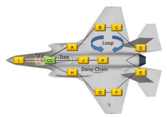
A basic analysis of the AS5643/1394 Beta standards can help designers make their decision about its viability. Each AS5643 bus typically consists of two types of nodes; a Control Computer (CC), also referred to as a Vehicle Management Computer (VMC) and Remote Nodes (RN), also referred to as a Line Replaceable Unit (LRU). Typically, there is only one Control Computer per 1394 bus and multiple Remote Nodes (Sensor, actuators, FADECs, Remote I/O, etc…). Control Computer and Remote Nodes may be connected to optimize the system implementation requirements for weight, volume and redundancy. Weight is minimal, as is volume. 1394 Beta only requires two differential pairs per port, or one TX and one RX per fiber optic port. 1394 Beta allows the system architect to optimize for both weight and redundancy by supporting a mixture of daisy chaining, tree, loop and star topology configurations. 1394’s flexible cable topology support allows the system implementer to optimize cable routing to meet weight/volume and robustness requirements and, unlike star or switched technologies homerun cabling is not required. Designed to be low cost and low power, 1394 Beta may be implemented using industry standard 8b10b SERDES with LVDS-type differential signaling. Both are industry standard for serial I/O and therefore power/performance optimized SERDES implementations are available in both standard silicon and many FPGA families. Currently, almost all aerospace and defense applications use standard COTS 1394 silicon with all the cost and ecosystem benefits that implies; development and production test tools/equipment already exist, multiple software stacks operating under multiple OSs are widely available and, if desired, FPGA PHY and Link IP cores are also available. Additionally, the digital logic in most S400 PHY and Link designs operate at less than 50MHz, which reduce switching currents and help make 1394 Beta FPGA friendly.
AS5643 defines the use of both passive and active transformers to be used with standard 1394 Beta. These transformers provide the electrical isolation necessary to meet the stringent aerospace and defense requirements such as RTCA/DO-160 lightening susceptibility. The active transformers boost the guaranteed minimum differential signal amplitude from 600mV(P-P) to 1100mV(P-P) allowing cable lengths of greater than 30 meters at 500Mb/s to be achieved.
In terms of software requirements, AS5643 architecture keeps Remote Node (LRU) 1394 related software to a minimum. AS5643 architecture specifies pre-assigned static addressing, using 1394 channel numbers, which significantly reduces the plug-n-play requirements of standard 1394 and eliminates the need for device discovery software after power-up and bus resets. The reduced complexity increases robustness by making the software simpler and it allows for communication to resume immediately after a short (1.3usec) or long (166.7usec) bus reset. Simpler software means less lines of code, which means less time and cost to certify the LRU for flight. Finally, the specification is architected to scale with speed and topology, keeping changes to software at a minimum.
Several A&D programs have selected Mil1394 and have incorporated up to 60 devices per airplane. The unprecedented use of a high speed (491.52Mb/s) serial interface has very effectively proven the capability of AS5643/1394 Beta in modern aircrafts, and has opened the door for higher bandwidth communication between the Control Computer and LRUs. While I/O bandwidth is important, system level deterministic behavior is required for most vehicle system networks and AS5643 coupled with 1394 Beta provides the required deterministic behavior.
Using 1394 Beta’s asynchronous stream capability, AS5643 creates a programmable rate-based (time-sliced) protocol that meets the rigorous requirements of advanced aerospace and defense system design all while using COTS silicon. When looked at from a system view, AS5643/1394 Beta is an ideal solution for safety-critical, deterministic (hard real-time) distributed control. As such, it provides the guaranteed latency and jitter needed to ensure that the data required for distributed control functions are delivered in a timely and predictable manner. Today there exists an excellent set of infrastructure products including development tools, test tools and equipment, software stacks, IP Cores and simulation environments. The result is reduced risk, reduced cost, and a reliable, deterministic system with a high level of robustness.
AS5643 protocol defines a time synchronization and Anonymous Subscriber Messaging (ASM) protocol. Time synchronization is accomplished by the Control Computer sending out Start of Frame (STOF) packets at the network profile specific frame rate (typically 80Hz or 100Hz). The transmission jitter of the STOF shall be within +/-0.1% of the fixed frame rate (e.g. for a 10 millisecond frame rate the STOF shall be transmitted +/-10μsec). All Remote Nodes receive the STOF packets and base the assigned offset times to the received STOF packets. The ASM messages are transmitted at the network profile assigned offset times relative to the STOF. This allows the receiving node to deterministically anticipate and therefore guarantee resources are available to process the received messages.
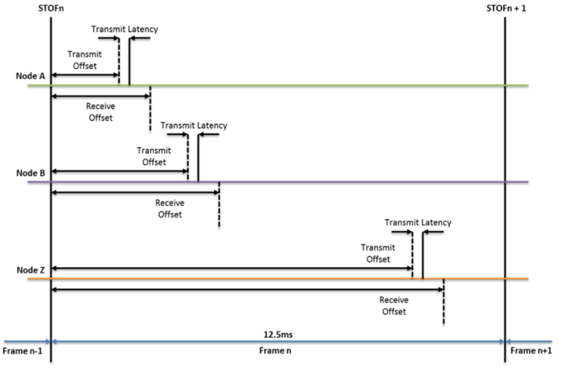
The network profile system architecture determines the frame rate and offset time for every node on the 1394 Beta bus. The offset times may be adjusted during the AS5643 initialization process. The deterministic architecture of AS5643 allows the system architect to design a deterministic system comprised of many devices.
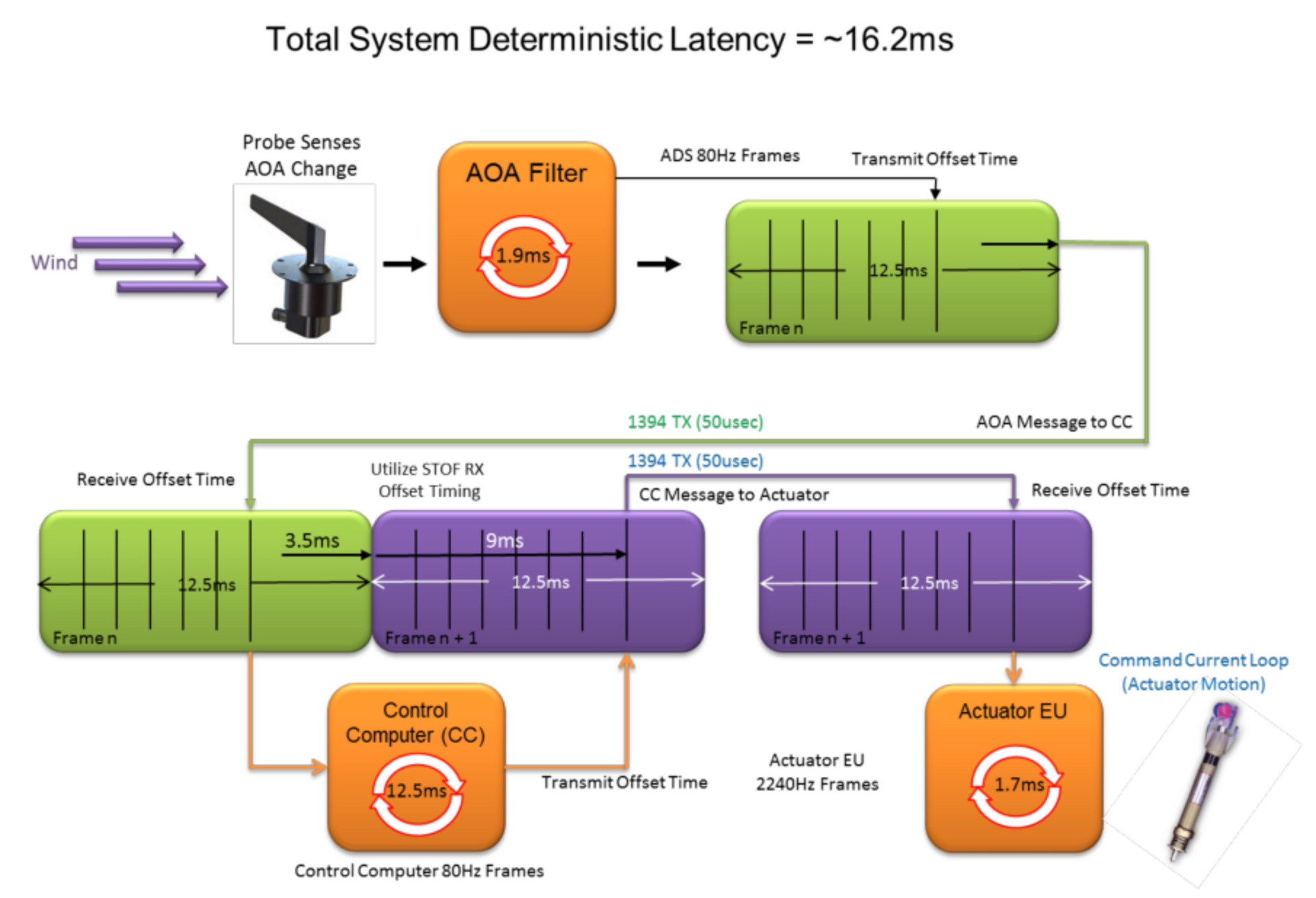
The figure below shows how both the system requirements and AS5643 frame rate are combined to determine the total system deterministic latency. The system latency is calculated from the Angle of Attack sensor (AOA) where its data is processed (1.9ms) by the AOA filter and placed into an AS5643 ASM message and transmitted at the appropriated transmit offset time. The packet makes its way across the 1394 Beta bus (~50usec) to the Control Computer
(CC) which processes the received data (12.5ms) and formulates the ASM message to be transmitted to the Actuator EU at the appropriate transmit offset time. Finally the actuator receives the message and processes the data causing the actuator to move.
From a system design point of view the AOA sensor and filter subsystem designer can understand and design to the system requirements thus guaranteeing its data will be ready to transmit at the desired time. The CC designer can now predict
when it is expected to receive the AOA sensor data and can guarantee to have resources available to process the data when it arrives. The time the CC has to process the data is also deterministic and specified. Once the CC AOA data has
been processed it is sent to the actuator EU as a specified offset time. This allows the actuator EU to anticipate when the message will arrive and guarantee it has the required resources available to service the message and adjust the actuator at the system required time. In this simple example the deterministic behavior extends throughout the complete system from the AOA sensor through the CC and finally to the actuator EU and AS5643/1394 Beta provides the facilities to make it happen.
For dual or triple redundant network architectures, the AOA LRU may be attached to two or three Control Computers. The AOA LRU sends its message data to each Control Computer it is attached to. The Control Computers process the received data and compare the result before sending messages to the Actuator LRU. This redundancy provides the fault tolerant behavior required for flight control.
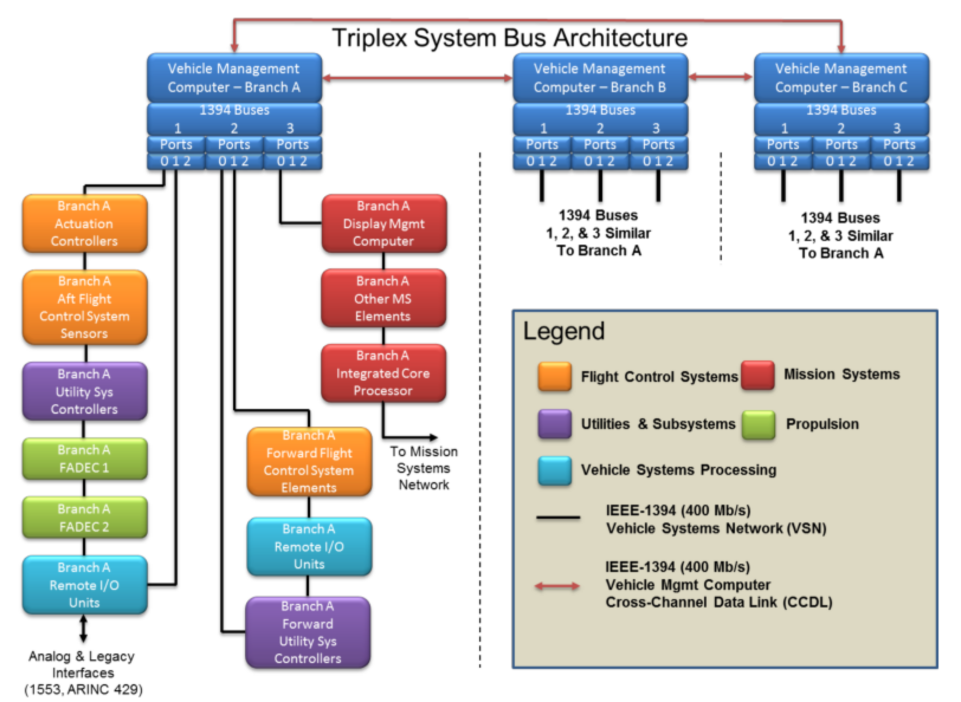
Fault isolation and recovery capabilities include cross-channel interconnectivity, with three CC branches (A, B, and C), which are connected via separate 1394 Beta buses. All three branches process data simultaneously and constantly compare results to assure data integrity. In cases of divergent data, two processors can “vote” one processor or signal out.
AS5643’s use of looped topologies and redundant bus architecture means that even if a single node fails, synchronized communication continues between the remaining nodes. Fault detection, containment, and tolerance are provided via the voting protocol, message status, application level consistency checks, and data integrity checks implemented in the hardware. Each ASM message includes several robustness features including header and data CRCs to catch 1394 bus level errors, node level health status information, heart beat count to help verify high-level functions are operational and Vertical Parity Check (VPC) to verify application level integrity.
AS5643/1394 Beta’s list of features and functions clearly indicates its suitability for many aerospace and defense applications including the hooks required to define a completely deterministic system architecture with redundant loop and network bus capability. Fault tolerance coupled with low and system level error detection built into the standard help system implementers define a predictable and cost effective implementation.
|
IEEE-1394b Interface Requirements for Military and Aerospace Vehicle Applications |
SAE | |
|
S400 Copper Media Interface Characteristics Over Extended Distances |
SAE | |
|
IEEE-1394b for Military and Aerospace Vehicles - Applications Handbook |
SAE | |
|
Test Plan/Procedure for AS5643 IEEE-1394b Interface Requirements for Military and Aerospace Vehicle Applications |
SAE | |
|
Test Plan/Procedure for AS5643/1 S400 Copper Media Interface Characteristics Over Extended Distances |
SAE |
|
Combining AS5643 and IEEE 1394b – the Rise of the Machine (2015) |
Mourn (FlightWire) Sanders (LMCO) |
| Bai (Honeywell) | |
| A flexible, deterministic solution for A&D applications (2013) |
Mourn (DapTechnology) |
|
SAE AS5643 and IEEE-1394 Flexible Deterministic Solution for Aerospace and Defense (2014) |
Mourn (DapTechnology) |